Four guide wheels would locate the enclosure into the ceiling of the Driving Motor cab.
Notice that there is a small aperture in the underside of the enclosure...
With the aperture slid back, the number 10 is visible through the inspection window. Rather than having whole destinations listed, the 1983 Stock destinations were depicted with unique number codes from 1 - 10.
The codes and their corresponding stations, along with their position on the blind are listed on a plate attached to the rear panel of the enclosure. To the right of the plate is the reason that this blind does not have a hand crank - these three buttons operate an internal motor that winds the blind mechanism clockwise or anti-clockwise, depending on the desired destination. This arrangement was unique to the 1983 Stock on the Underground, with subsequent stocks (including the 1986 Stock prototypes) featuring all-electronic destination displays.
No car number is provided on the rear panel, but the number ‘3702’ is written in faint pencil beneath the ‘No unauthorised person...’ warning, which may have been the Driving Motor from which this enclosure was removed.
The manufacturer of the blind...sorry, ‘Indicator’, enclosure is situated at the other end of the rear panel. Evershed & Vignoles was taken over by Avo Ltd in the mid-1980s, and is known as Megger these days - a very familiar name in the world of electrical test equipment.
Opening the hinged rear panel reveals a far more technical-looking interior to this enclosure when compared to earlier products. The internal frame for supporting the blind mechanism is gone, with the roller spindles now being attached to the enclosure directly. An advantage of the electrically-operated blind mechanism is the considerable reduction in weight, but that is definitely the only positive point!
A nineteen pin connector is attached to the side of the enclosure (though only seven of the pins are fitted). Four of these are for the lamp, two are for the motor control and the last provides an earth bond to the metallic structure of the enclosure.
The seven salmon-coloured wires have coloured tags applied to their ends - this allows the individual wires to be traced throughout the enclosure, as the other ends of the wires contain matching tags.
The four lamp wires pass straight to the other end of the enclosure, where they terminate into an insulated block connecting them to the two lampholder wires.
The 20 Watt fluorescent lamp dates to September 1997.
With the lamp removed, more salmon wires connect the motor control buttons to the internal circuitry.
Removing a cover reveals the Printed Circuit Board that controls the motor operation. An MJ10003 Darlington transistor surrounded by a large heat sink takes up much of the space here.
The motor is sandwiched between the two rollers. A weighted frame attached to its rotor pushes the gear in the direction of one roller or the other, depending on the direction that the motor is turning at the time.
Naturally, with this being a very different setup in comparison to the destination blinds acquired earlier, I was keen to bring this unit back into use as quickly as possible. The first challenge was finding a suitable connector for the multi-pin socket on the side of the enclosure. Thankfully, this is quite a common type of connector in industry, and is known as "MIL-Spec". After speaking to representatives from Amphenol and Glenair (two companies that produce such products), a Glenair MIL-DTL-5015 (RS Components’ part code 513-3341) was purchased, followed by a seven-core heavy-duty cable intended for use in caravan installations. The corresponding internal wires were traced back to the inside of the connector; helpfully, the individual pins are identified by letters from the alphabet. I drew out the following table as a way of reminding me of the purpose of each pin, along with its labelling colours, and the eventual core colour from the supply cable - please note that I have ignored the recommended purpose for each core colour on a DC circuit.
| Internal Wire Colour Code | Colour Code Number | Connects To | Connector Letter | Core Colour |
| Brown / Black | 1 / 0 | Lamp 1 | D | Black |
| Brown / Brown | 1 / 1 | Lamp 2 | C | Blue |
| Brown / Orange | 1 / 3 | Lamp 3 | B | Brown |
| Brown / Yellow | 1 / 4 | Lamp 4 | A | Green |
| Brown | 1 | Motor Positive | G | Red |
| White | 9 | Motor Negative | F | Yellow |
| Brown / Red | 1 / 2 | Earth | E | White |
The MIL-Spec connectors are designed to have their cables crimped to internal pins; however, crimping tools for this equipment are expensive, and so the cores were soldered into place instead. The connector can only be fitted one way around, thanks to a notch in its top. The collar surrounding the multiple pins rotates, with the blue dots revealing the positions of the three internal locking pins.
Once the connector is aligned with the receptacle on the destination blind enclosure, it is locked into position by rotating the collar until the blue dots align with the yellow dots on the receptacle; a click confirms engagement.
Owing to there being no operating voltage stated anywhere on the motor circuit, working out the voltage was difficult, particularly given the lack of any working 1983 Stock units. Initial enquiries suggested that the voltage would be 24 Volts (DC), but following discussions with individuals who are more familiar with the internal voltages of Underground stock, including with London Transport Museum staff, the operating voltage was believed to be around 50 V. The only way that I would know for sure would be to connect the motor and run it at a very low voltage initially, and then increasing it gradually until it worked satisfactorily. A bench power supply was sourced for this test, with the voltage being set to 12 V initially. When this yielded no movement, the voltage was increased to 24 V, but still, the motor did not rotate. Increasing the voltage to 35 V, however, did start it moving; albeit, very slowly. I guessed then that the voltage must be 50 V, and so increased it to the maximum - this worked far more reliably! The video below demonstrates the system being operated on test - notice that the normal speed is still rather slow, but becomes more acceptable when the Fast button is pressed.
An enclosure that was capable of accommodating a transformer for the motor circuit, along with a suitable ballast for the lamp was purchased, and the components installed inside. A 48 V DC transformer (the black object located top-left) was the closest alternative to the required 50 V, while a high frequency electronic ballast for 2 ft (600 mm) lamps was fitted below.
The blind enclosure interior was given as best a cleaning possible without disturbing any of the wiring. A new T8-sized 9 W LED lamp was fitted, complete with narrower Terry support clips.
The blind enclosure was attached to a length of wood that was (conveniently) the right length to allow it to be positioned above the stairs. Although pictured with cable ties holding it in place, the enclosure will be secured with brackets in time. As can be seen, the lamp circuit was operational here.
The lamp provided sufficient illumination for the number identifier on the rear window to be visible too (though giving the glass a good clean beforehand helped!).
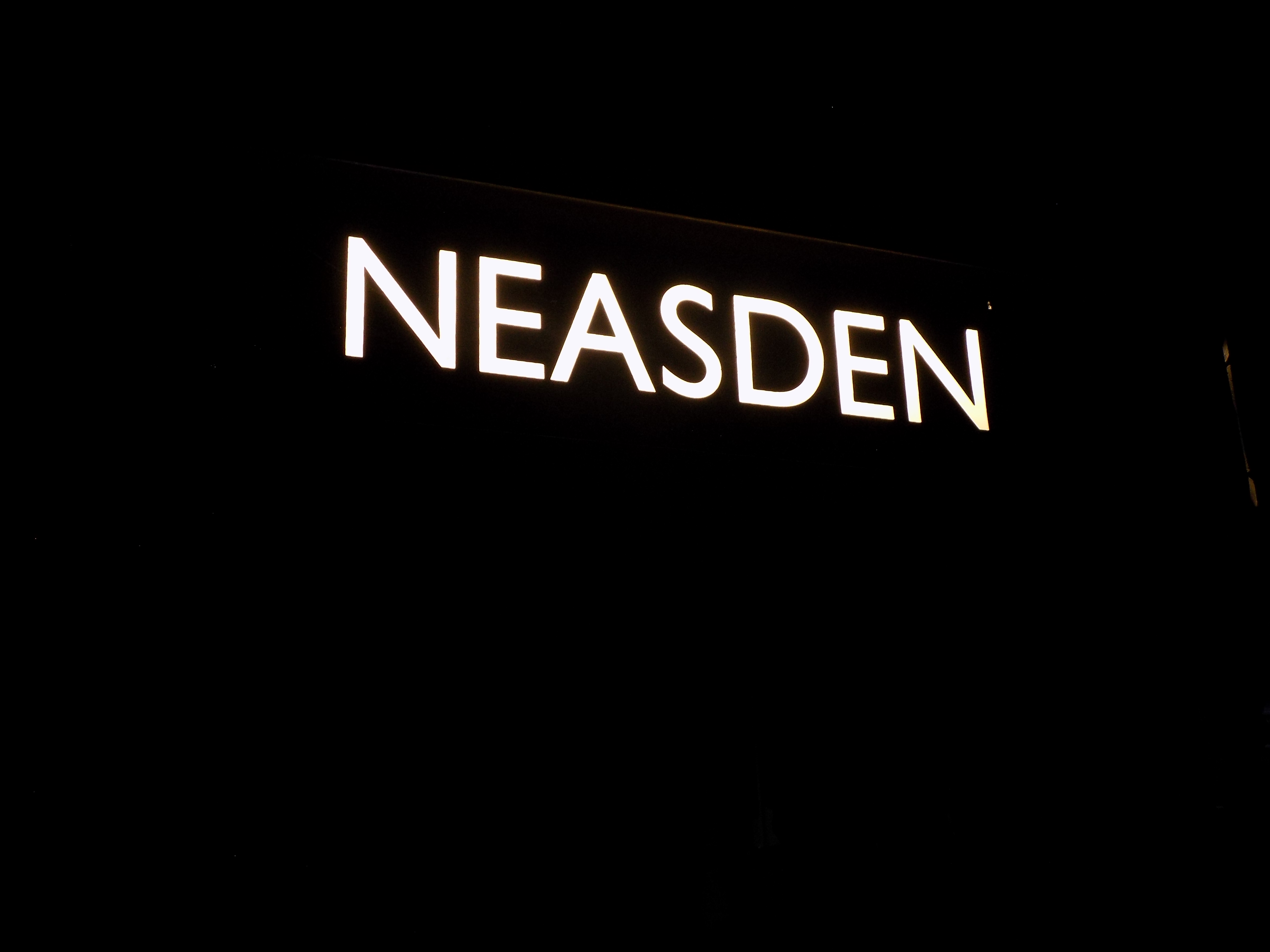
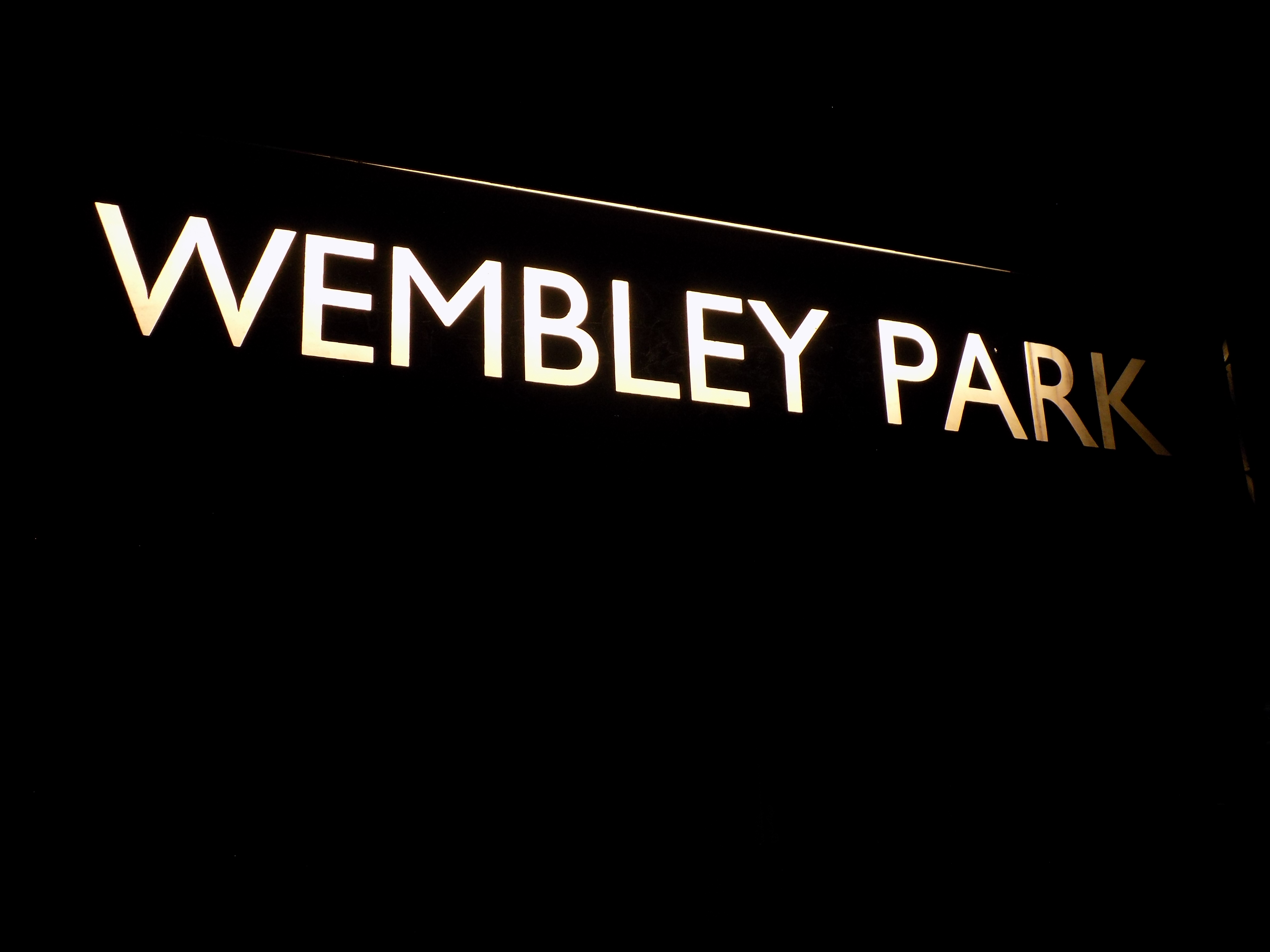
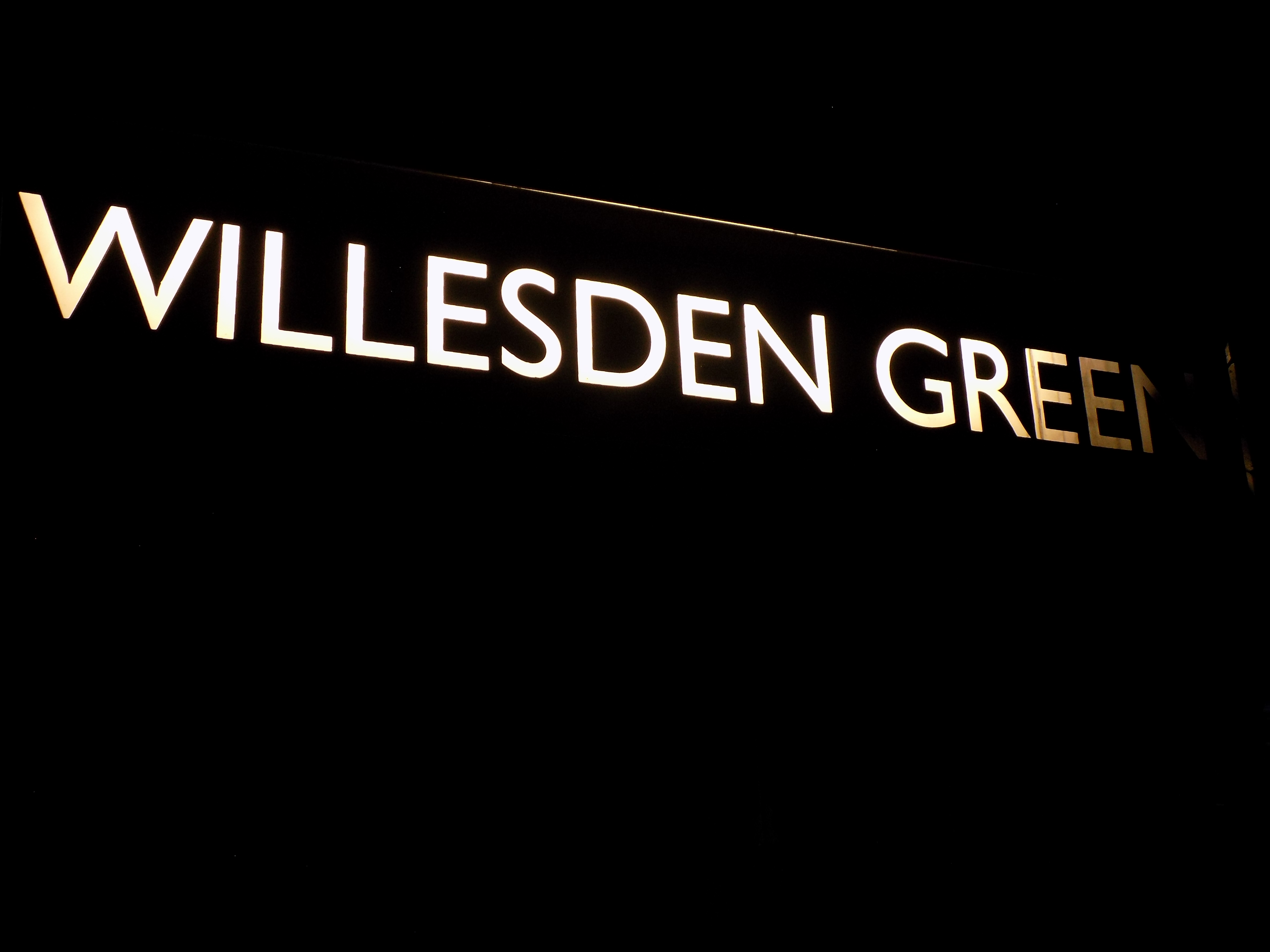
The full complement of destinations is displayed below; click the thumbnail image to download individual destinations (note - the full-sized images are 5152 × 3864 pixels in size). Notice that the shadow of the motor is cast on the longer destinations.
| Canons Park | Neasden | Stanmore | Wembley Park | Charing Cross |
 |
 |
 |
 |
 |
| Willesden Green | West Hampstead | Finchley Road | Special | Not In Service |
 |
 |
 |
 |
 |
A video demonstrating the blind in operation is available below:
CLICK HERE TO MAKE A MONETARY DONATION
© 2008 - English Street Lights Online