The Halo bears a slight resemblance to the earlier 'Springbak' bollard from Haldo, although, it relies on the springiness of its base, rather than on dedicated steel springs (as with the Springbak), in order to effect the rebounding process. Another difference is that the Springbak featured an internal lighting spine up its centre, whilst the Halo employed a base-lit system that incorporated three 10 Watt PL-S type lamps positioned vertically, in order to provide illumination up the bollard.
A lug in the back of the bollard is used to secure it to its base.
A grub screw positioned at this hole would be tightened, which in turn, would cause for an internal stainless steel circular wire to compress around the bollard base, securing the top in position.
At some point, the plastic top section of the bollard has cracked.
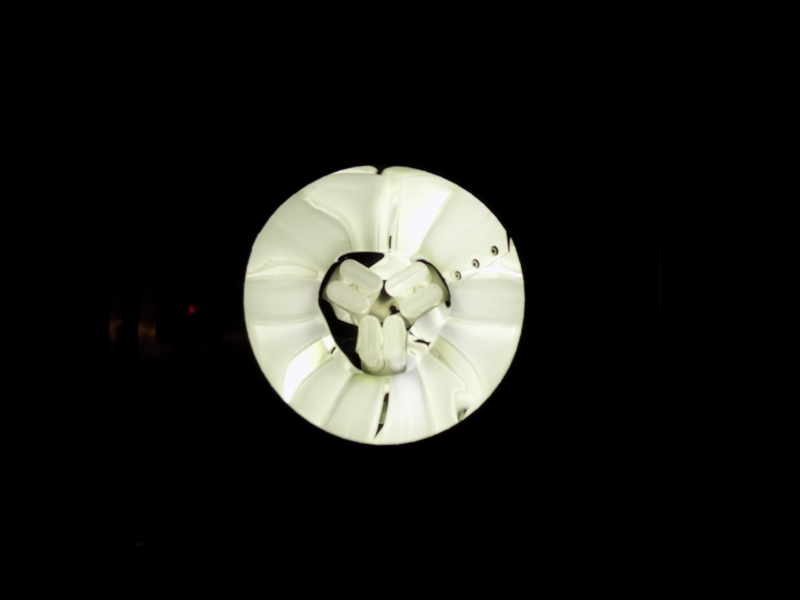
The inside of bollard is white, in order to maximise reflectance.
A small section of the internal circular wire is seen here. Originally, this terminated into a welded steel wedge that fitted into the lug; however, as this was damaged (and the grub screw missing), I removed it.
The view looking right up the bollard is reminiscent of the start and end of many Warner Bros. cartoons!
New reflective tape was wrapped around the bollard's neck - it is seen here positioned alongside its plain-aspect Springbak sibling.
The reflective tape is 50 mm in width; a standard size.
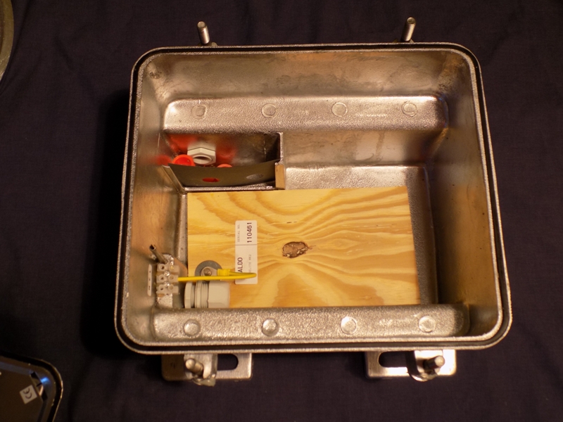
Owing to the non-standard design of the base unit, a 440 mm (1 ft 5.32 inches) diameter piece of medium-density fibreboard was placed beneath the bollard shell; this being the same inner diameter of the lowest concentric ring. An E27 lampholder and 7 Watt LED R63 reflector spotlight lamp were positioned in the centre of the board, and connected up.
Conveniently, the supply cable fitted through the old grub screw hole with ease. In the bollard's latter years when installed on the road, two small holes had been drilled in the lower section of the shell, and the top secured to the base with screws. These holes were re-used, as the same method is used to secure the shell to the board. The use of a reflector lamp with a wide beam angle allowed the vertical yellow tube to be illuminated, along with the head section.
Testing with my energy monitoring device revealed the following results:
| Test Voltage (V) | Current being drawn at full power (A) | Measured wattage (W) | Apparent Power (VA) | Frequency (Hz) | Power Factor | True Power (W) | Difference to rated wattage | Percentage Difference |
| 246.4 | 0.06 | 8 | 15 | 49.9 | 0.58 | 8.57 | 1.57 | 22.50% |
In February 2020, an unused Halo baselight was obtained. This comprises a standard Haldo base box, with a large circular top section that the Halo top would fit onto.
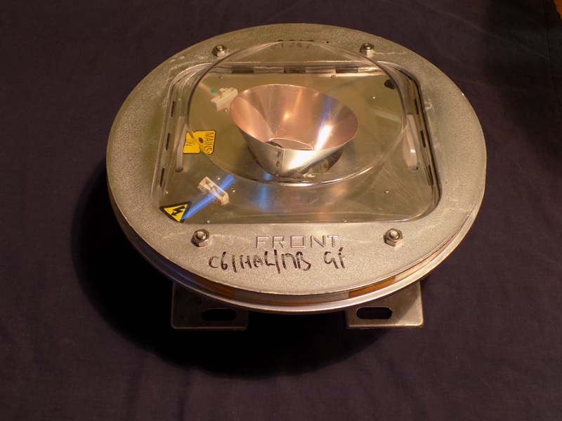
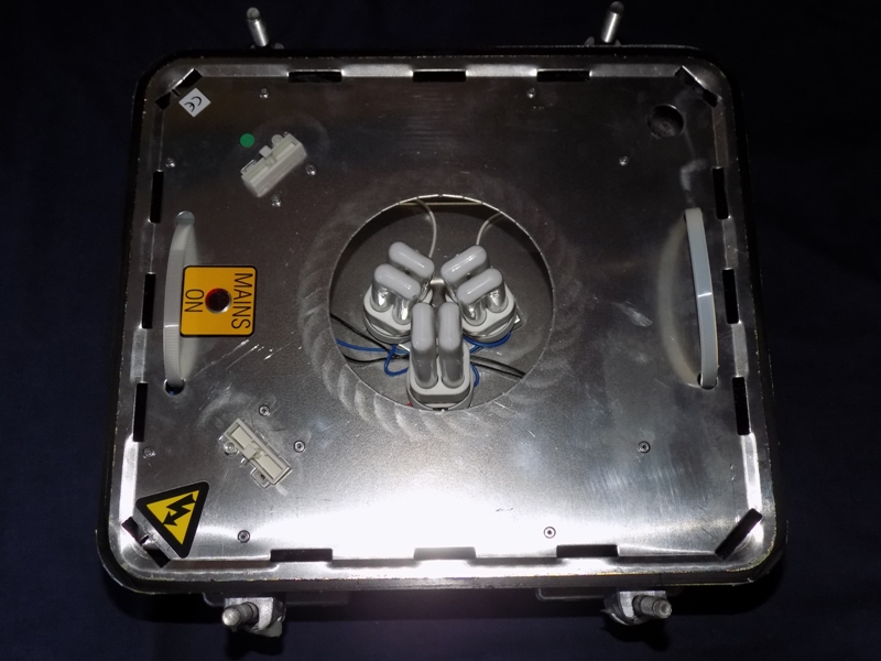
With the four locking nuts removed, the circular top lifts away from the base, revealing the lighting unit. Three G24d-1 lampholders are situated in the middle, surrounded by a polished aluminium cone, for directing the combined light output up the Halo's neck section. The lighting unit is somewhat elaborate, with a neon indicator light signifying the presence of mains voltage.
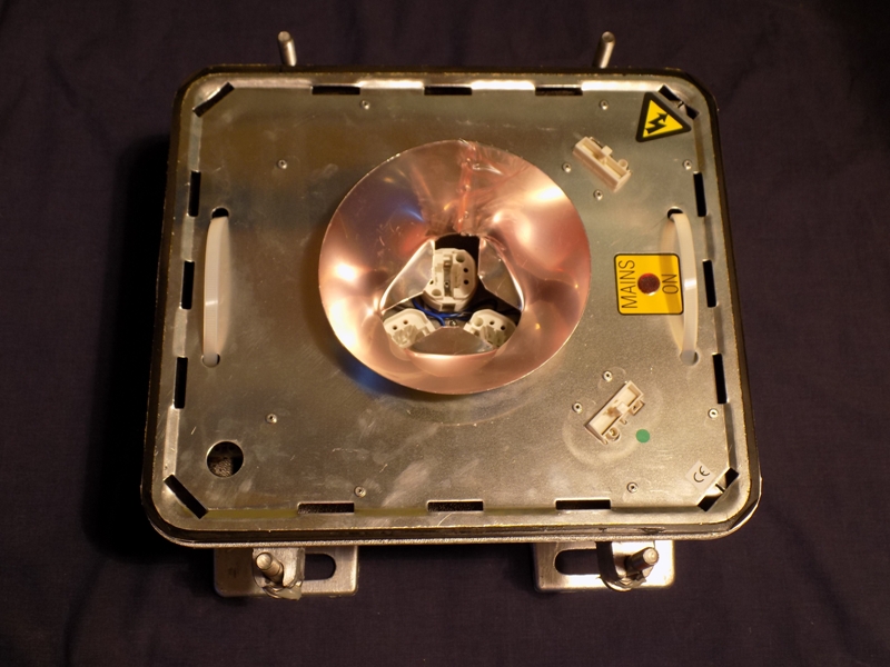
The conical reflector perches on top of the lighting unit, although it is secured by the three lamps pressing into it ordinarily.
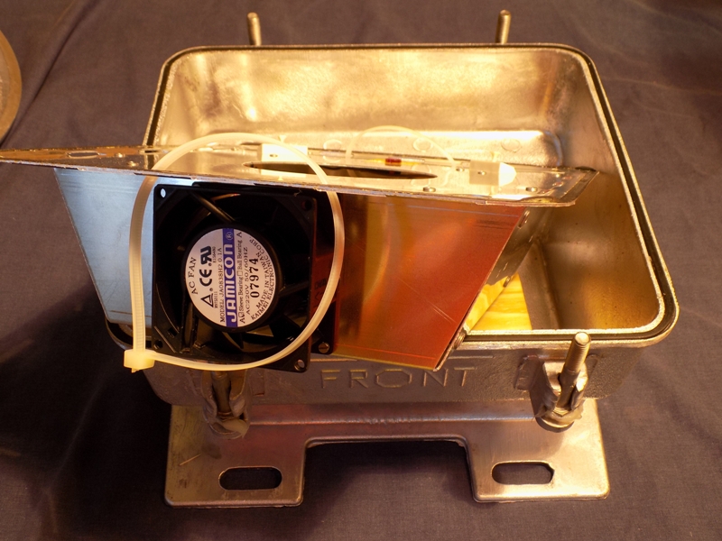
The lighting unit also incorporates a small fan, which, I assume, is intended to dissipate the heat generated by the lamps and ballasts, though as there is no means of venting the heat away from the base, the need for the fan is questionable - I suppose that the intention is to heat up the base box, which, ordinarily, would disperse into the body of ground surrounding it.
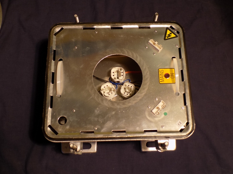
The lighting unit can be removed by pulling on the two cable ties located on either side of it, revealing the interior of the base itself. The connector located bottom-left is intended to push onto another connector on the same position in the lighting unit; thus, allowing (supposedly) easy replacement of a defective lighting unit.
The three 10 Watt lamps are arranged in a Y-shaped formation.
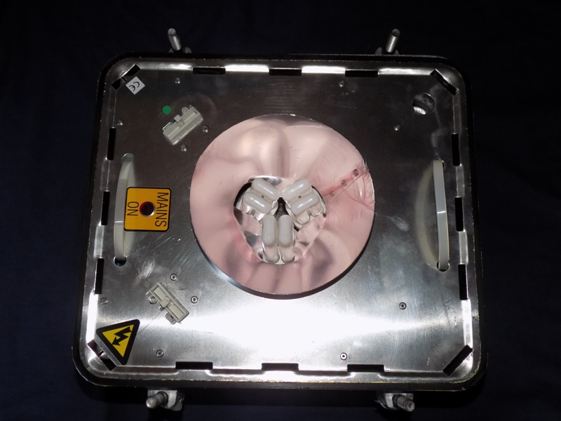
This photograph shows how the addition of the reflector increases the overall surface area. The protective plastic sheeting was still fitted to the reflector at this stage.
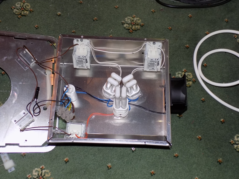
I hadn't expected to picture the inner wiring of the lighting unit, as the top section is riveted to the lower section. As things turned out, I had to drill out all of the rivets and replace the connector, as one of the pins broke as the lighting unit was lowered back in to the base box, and the only way to carry out the replacement was to remove the top section. Therefore, this view is a bonus (you lucky lot!). There are two lamp circuits, with one protected by its own fuse, while the other two share a fuse.
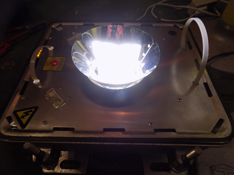
With the plastic sheeting removed, and the lighting unit powered up, this is how the baselight appears from above.
Notice that the neon indicator light is illuminated too.
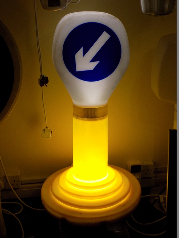
The Halo was introduced to its baselight; the only difference between my makeshift solution and the 'official' means of illumination being a slight increase in illumination to the sprung lower part of the bollard.
Re-testing the power consumption proved that the baselight was a far less efficient solution than the LED spotlight had been (assuming an overall wattage of 30 W for the three lamps)!
| Test Voltage (V) | Current being drawn at full power (A) | Measured wattage (W) | Apparent Power (VA) | Frequency (Hz) | Power Factor | True Power (W) | Difference to rated wattage | Percentage Difference |
| 250.8 | 0.62 | 77 | 155 | 49.9 | 0.49 | 76.19 | 46.19 | 153.98% |